

















How Can Rooftop PV Fire Risks Be Reduced? A Galaxy Array Safety Design Guide
October 29, 2026


A safer rooftop photovoltaic array starts with the complete installation: the electrical circuit, mounting interface, roof construction and access for inspection and maintenance. For GoodWe Galaxy G4 frameless bonded and G5 framed clamped applications, the key design questions are how an electrical fault could develop, what materials it could ignite, and how the resulting risk can be identified and managed safely.
What Did the Los Angeles Warehouse Fire Investigation Establish?
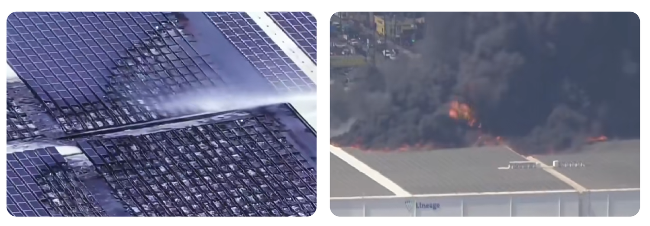
The fire at the Lineage cold-storage warehouse in Boyle Heights, Los Angeles, on 17 June 2026, provides a serious reason to revisit these questions. The Los Angeles Fire Department's report records approximately 12,400 rooftop PV modules.
Its September announcement confirmed an origin on the roof at or near solar panels and an electrical event in that area, while retaining an undetermined cause classification. This does not establish a particular connector defect, module technology or mounting gap as the cause.
How Should Ignition Risks and Fire Spread Be Assessed Separately?
Electrical defects can produce local heating or arcing. The resulting fire depends partly on the materials and geometry around that fault. Rooftop PV therefore needs both electrical fault prevention and consideration of how fire could spread through the building envelope.
Record the roof covering, insulation, deck, penetrations and existing compartment boundaries. A metal outer sheet alone does not reveal the combustibility of a sandwich-panel core. For cold stores and other high-consequence buildings, involve the roof specialist, fire engineer and insurer before fixing the array layout.
Module fire-test classification is evidence for a defined test configuration. It is not an approval of every roof assembly or installation method. Confirm the exact model, construction, mounting conditions and supporting report before making a fire-performance claim. This series makes no blanket fire-class claim for G4 or G5.
How Should Rooftop PV Arrays Be Designed for Safe Access and Fire Separation?
Draw access routes, rooflights, smoke vents, drainage paths and fire separation before maximising module count. Keep electrical connections inspectable and provide a practical replacement route. Do not bridge compartment boundaries with modules or cable routes without an accepted fire strategy. Required dimensions depend on the jurisdiction and building; Figure 1 deliberately gives no universal setback.
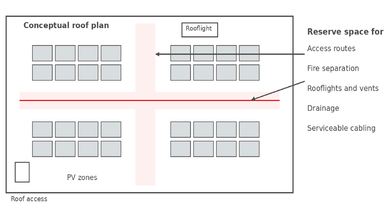
Figure 1. Conceptual roof planning zones. The local design must determine route widths, separation distances, drainage clearances and load-rated access. This is not a construction layout.
How Can DC Circuit Design Help Reduce Rooftop PV Fire Risks?
Check cold-condition string voltage, hot-condition operating voltage, input current, parallel-string reverse current and equipment limits using the actual module and inverter data. Size cables for installation temperature, grouping and routing, and coordinate overcurrent protection, earthing, isolation and surge protection. IEC 62548-1 provides an array-design framework; apply the locally adopted requirements.
Specify connector manufacturer and mating family at procurement. “MC4 compatible” is insufficient evidence. Australian guidance requires mating connectors from the same manufacturer that are designed to mate together. Confirm the supplied connector on each module variant and extension lead rather than assuming one connector across the Galaxy family.
Assess arc-fault detection and interruption where required or selected for the project. Confirm the exact inverter function and compatible configuration. Protection complements workmanship; it does not make defective connections acceptable or guarantee that every fault will be detected.
How Should Galaxy G4 Bonding and G5 Clamping Interfaces Be Assessed?
For G4 bonding, qualify the actual roof surface, adhesive, preparation and support arrangement. Protect the junction box and rear cable exit from contact, trapped adhesive and mechanical pressure. Keep cables and connectors away from water paths and arrange inspection before the interface becomes concealed. Do not modify coatings or add support materials without the approved installation method.
For G5 clamping, the product flyer identifies rail and railless options. Select the documented clamp, frame engagement zone and tightening procedure for the precise module and supporting structure. Prevent frame edges and clamp hardware from pinching cables. Verify any required bonding path; metal contact alone should not be assumed to provide dependable electrical continuity.
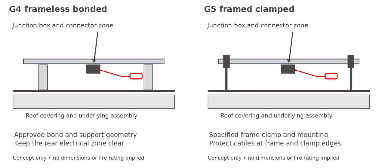
Figure 2. The two interfaces require different mounting checks but share the need for protected, accessible rear electrical components. Supports, gaps and clamp positions are illustrative, not dimensioned installation instructions.
A larger air gap can affect normal operating temperature, but it is not a universal fire remedy. Fire behaviour depends on the roof materials and geometry of the complete assembly. Do not raise a bonded module on improvised spacers or alter a clamp arrangement to chase an assumed fire benefit. Any change needs review for attachment loads, drainage, electrical clearance and applicable fire evidence.
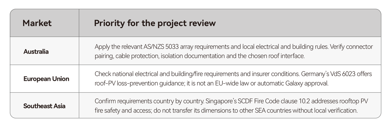
Which Rooftop PV Fire-Safety Requirements Apply in Each Market?
Use the following as a design-review map. The project register should name the applicable edition, authority, evidence and responsible designer. International standards, insurer guidance and statutory requirements have different roles.
What Five Safety Checks Should Be Completed Before Design Approval?
Before releasing the design, confirm that:
Roof build-up and fire strategy are documented, including concealed combustible materials.
The exact Galaxy model and approved bonding or clamping interface are identified.
String calculations, connector pairings and electrical protection are coordinated.
Inspection access, drainage and replacement routes remain usable after installation.
Unresolved product, roof or authority questions have an owner and prevent affected work from proceeding.
GoodWe provides product information and documented interface requirements. The EPC is responsible for coordinating the installation with the relevant building, electrical, and fire-safety specialists.
A lightweight module can help address roof-load constraints, but that benefit must be incorporated into a comprehensive safety design.
*Technical scope: educational guidance, not project design approval, installation authorisation or a warranty extension. Qualified local professionals must verify the current product documents and project requirements.


